106 Results
View results:
Sort by:

The data exchange between RFEM 6 and Allplan can be done using various file formats. This article describes the data exchange of a determined surface reinforcement using the ASF interface. This allows you to display the RFEM reinforcement values as level curves or colored reinforcement images in Allplan.

The fatigue design according to EN 1992-1-1 must be performed for the structural components subjected to large stress ranges and/or many load changes. In this case, the design checks for the concrete and the reinforcement are performed separately. There are two alternative design methods available.

This example shows you how to quickly determine the buoyancy or the uplift limit state of a vessel in RFEM.

The automatic surface reinforcement design process determines a surface reinforcement that covers the required amount of reinforcement.
,_Table_22.5.5.1_ACI_318-19.png?mw=640&hash=7e50d54e01238943fe1c691c0aa197d9b2fa8511)
With the most recent ACI 318-19 standard, the long-term relationship to determine the concrete shear resistance, Vc, is redefined. With the new method, the member height, the longitudinal reinforcement ratio, and the normal stress now influence the shear strength, Vc. This article describes the shear design updates, and the application is demonstrated with an example.

Using the Concrete Design add-on, concrete column design is possible according to ACI 318-19. The following article will confirm the reinforcement design of the Concrete Design add-on using step-by-step analytical equations as per the ACI 318-19 standard, including the required longitudinal steel reinforcement, gross cross-sectional area, and tie size/spacing.

Complex structures are assemblies of structural elements with various properties. However, certain elements can have the same properties in terms of supports, nonlinearities, end modifications, hinges, and so on, as well as design (for example, effective lengths, design supports, reinforcement, service classes, section reductions, and so on). In RFEM 6, these elements can be grouped on the basis of their shared properties and thus can be considered together for both modeling and design.

Foundations including dimensions can be saved as a template in a user-defined database.

It is possible to edit a reinforcement layout or an existing reinforcement directly in the reinforcement's 3D rendering.

In RFEM 5 as well as RSTAB 8 in RF-/FOUNDATION Pro, you can save the foundation dimensions for all five foundation types as foundation templates in a user-defined database and use them later in other models.

In RF-/FOUNDATION Pro, the foundation design requires the definition of the corresponding loading (load cases, load combinations, or result combinations) for different design situations (STR, GEO, UPL, or EQU).

In RF‑/FOUNDATION Pro, reinforcement drawings are displayed after designing the foundation, where you can record all necessary structures of the reinforcement steel.

When modeling structural bearing systems, especially hall structures, some substructures of a foundation with no influence on the rising structure are not modeled in RFEM/RSTAB. In the case of hall structures, these are, for example, reinforced concrete floor slabs, strip foundations, and the ties between column foundations.

An elastic foundation can be applied to a member. Thus, the influence of the soil is usually included in the modeling. Member elastic foundations can only be defined for the "Beam" member type.

In the case of using slow‑curing concrete (usually for thick components), you can reduce the calculated minimum reinforcement by a factor of 0.85 to apply the load due to restraint, according to EN 1992‑1‑1, Section 7.3.2. However, a precondition for reduction is that the characteristic value of the strength development r = fcm2 / fcm28 does not exceed 0.3. Other key requirements for the application of this reinforcement reduction are specified explicitly in the final planning documents.

This article deals with the determination of the concrete reinforcement for a beam stressed by tension only according to EN 1992-1-1. The aim is to show the tensile load of a member-type element (without imposed deformations) and to define the concrete reinforcement in accordance with the standard's construction rules and provisions using the RFEM structural analysis software.

In RF‑/FOUNDATION Pro, the available reinforcing steel diameters can be adjusted by the user. The adjustment of the available rebar diameters works similarly to the same function in the RF‑/CONCRETE (Members) and RF‑/CONCRETE Columns add‑on modules.

The German Annex to EN 1992‑1‑1, the National Addition NCI to Article 9.2.1.2 (2), recommends to dispose the tension reinforcement in the flange plate of T‑beam cross‑sections on a maximum of one width corresponding to the half of a computed effective flange width beff,i according to Expression (5,7a).

In RF-/FOUNDATION Pro, the user can freely select the proportion of the relieving soil pressure by means of the factor kred.

In RF‑/FOUNDATION Pro, you now have the option to design a foundation at one or several nodes of the model.

In RFEM and RSTAB, different graphical representations of the foundation dimensions are available.

For foundation design, it is necessary to define the relevant loads for the respective design situations (STR, GEO, UPL, EQU).

For uniformly distributed loading according to EN 1992‑1‑1 (Eurocode 2), the design section for the shear reinforcement can be placed at the distance d from the front edge of the support. Thus for the shear reinforcement, the applied shear force is reduced to VEd,red. To analyze the maximum design shear resistance VRd,max, however, the total shear force is applied.

In RF‑/CONCRETE Columns, different methods are available for defining the minimum longitudinal reinforcement. The minimum reinforcement can be selected according to the design standard used and/or specified by the user.

When calculating foundations according to EC 7 or EC 2, different foundation types or sizes are usually used in one object. However, boundary conditions like the soil parameters, the materials for foundations, concrete covers, and the load combinations selected for design remain the same for all foundations, as a rule.

You can use the elastic support option to avoid singularities due to a fixed nodal support in RFEM. This can be defined directly in the dialog box of the nodal support as a column in Z. It is necessary to take into account the geometry of the column, the material, and the support conditions. Here, we want to look at the option of modeling the column as a surface foundation.

In RF-/FOUNDATION Pro, a graphical display of the result details is available. To see them, go to Window 2.2 Governing Design Criteria after the calculation. In the interactive graphic of this window, individual design-relevant values can be displayed for each design performed.
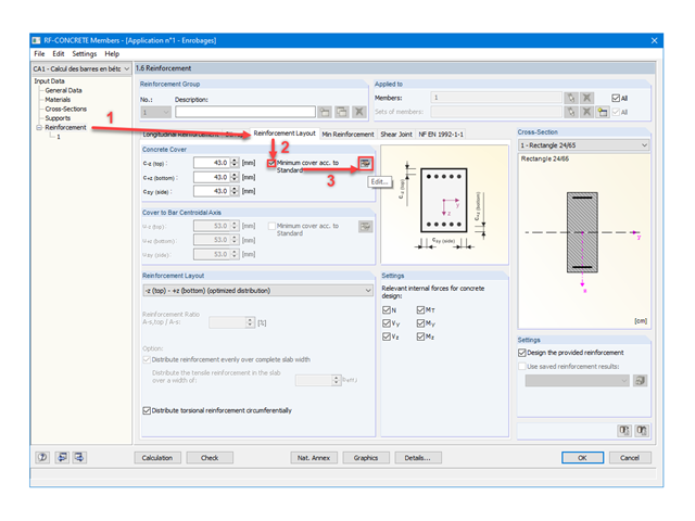
This article deals with the protection of reinforcement against corrosion defined according to EN 1992-1-1, also called concrete cover. The purpose of this article is to show how very many parameters defined in the Eurocodes for concrete reinforcements are considered in the RFEM structural analysis software.

If nonlinear effects - such as failing supports, foundations, member nonlinearities, or contact solids - are used in the model, you can deactivate them in the global calculation parameters.
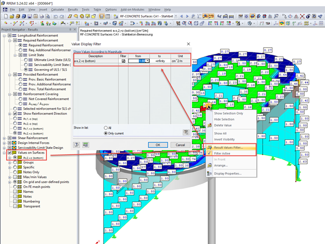
In many cases, it is necessary to filter the results for the display of values on surfaces so as not to show all the numbers. In displaying the reinforcement arrangement, you can, for example, hide values that are below the already used basic reinforcement.